




A design that looks perfect in CAD isn’t necessarily easy or economical to manufacture. Many of the costs that inflate production don’t come from major design flaws, but from small decisions that create unnecessary machining operations, complicate assembly, or increase maintenance effort.
This is where Design for Manufacturing and Assembly (DFMA) delivers real value. Beyond the familiar principles of reducing part count and avoiding unnecessarily tight tolerances, effective DFMA focuses on the practical details that improve manufacturability, simplify assembly, and reduce lifecycle costs.
This article highlights six often-overlooked design decisions that experienced manufacturing engineers consider early in the design process. Each one addresses a specific source of manufacturing cost or assembly inefficiency:
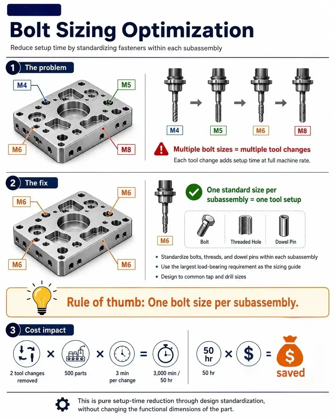
- Bolt Sizing Optimization: Eliminates unnecessary tool changes without compromising functionality.
- Material Standardization: Simplifies procurement while reducing inventory and material handling costs.
- Material Removal Awareness: Reduces machining time by designing around standard stock sizes.
- Guided Adjustment Mechanisms: Prevents rotational movement that conventional slotted holes cannot control.
- Shaft Undercuts at Steps: Ensures proper bearing seating and improves assembly reliability.
- Quick-Release Assembly Design: Reduces maintenance access time from minutes to seconds.
These are decisions that can be made during detailed design, before tooling is committed, and when engineering changes are least expensive and have the greatest impact on manufacturing efficiency. For designers working with fabricated components, many of these principles also apply to sheet metal design, where geometry has a direct influence on production cost.
TIP 01 | Bolt Sizing Optimization
The problem this solves
When a single assembly uses multiple bolt sizes M4, M5, M6, and M8, for example the machinist must change tools between each fastener operation. Every tool change adds setup time, and setup time is charged at the full machine rate, whether the spindle is cutting or not.
On a complex machined component, this can mean four or five tool changes that add no value to the part whatsoever. Multiplied across a production run, the cost accumulates quickly and it is entirely invisible at the CAD stage if the designer is not thinking about machine setup.
The fix
Standardize all bolts, threads, and dowel pins within a single assembly to one size wherever function permits. This does not mean the whole product uses one bolt size it means each subassembly uses one bolt size.
- Review every fastener in the assembly and identify the largest load-bearing requirement. Size all remaining fasteners to match it, or move to a single standard that covers all cases with acceptable safety margin.
- Dowel pins should follow the same rule. If the assembly uses 6mm dowels in one location and 8mm in another for historical reasons rather than functional ones, standardize to one size.
- Check with your machinist or CNC programmer on their standard tooling set. Designing to common tap and drill sizes (rather than obscure thread pitches) further reduces setup complexity.
Eliminating two tool changes per part on a run of 500 units at a conservative 3 minutes per change and a $120/hr machine rate saves $6,000 without changing a single functional dimension of the part. This is pure setup-time reduction through design standardization.
TIP 02 | Material Standardization
The problem this solves
When a design uses multiple plate thicknesses say 6mm for the base, 8mm for a stiffener, and 10mm for a mounting pad the fabricator must order and stock three separate materials. Each is a separate purchase order, a separate delivery, a separate cut length to manage, and potentially a separate supplier.
For the engineer, the difference between 6mm and 8mm plate may seem minor. For the fabricator costing the job, it is three-line items instead of one, with the associated overhead on each.
The fix
Where structural analysis permits, use a single plate thickness throughout an assembly. The extra material in a thicker-than-minimum plate is almost always cheaper than the procurement overhead and material handling cost of sourcing multiple thicknesses.
- Run your FEA or hand calculations for the minimum required thickness, then check whether rounding up to the next standard plate thickness allows you to eliminate a separate size entirely. In many cases, a 10% increase in section thickness has negligible structural or weight impact but eliminates a separate material order.
- Standard plate thicknesses vary by region and supplier coordinate with your fabricator before finalizing your drawing callouts. In the USA, common mild steel plate runs in 1/4″, 3/8″, 1/2″ increments; metric designs typically standardize on 6mm, 8mm, 10mm, 12mm.
- Apply the same principle to tube, bar, and extrusion stock. An assembly that uses 40×40 RHS and 50×50 RHS for different members can often be consolidated to one section size without compromising the design.
Material standardization directly reduces procurement waste. Unused offcuts of non-standard sizes are harder to reuse and more likely to go to scrap. A design that uses one plate thickness generates a single predictable offcut profile that is easier to nest efficiently and recycle.
TIP 03 | Material Removal Awareness
The problem this solves
Raw material whether bar stock, plate, or billet comes in standard sizes. When a designer specifies a final machined dimension that requires removing a large amount of material from a standard stock size, they are specifying machining time that adds cost without adding function.
A 50mm diameter shaft machined from 80mm diameter bar stock requires removing almost 40% of the material by volume. A 50mm shaft machined from 55mm bar stock removes less than 10%. Both produce the same final part. The difference is entirely in machining time and machining time is the most expensive operation in the manufacturing process.
The fix
When selecting final dimensions for machined components, check the available standard stock sizes first and design your nominal dimensions to minimize the removal ratio.
| Stock Size (bar) | Final Diameter | Material Removed |
| 80mm bar | 50mm shaft | ~ 60.94% by volume – expensive |
| 63mm bar | 50mm shaft | ~37% by volume – moderate |
| 55mm bar | 50mm shaft | ~17% by volume – efficient |
| 52mm bar | 50mm shaft | ~8% by volume – optimal |
The same principle applies to plate and block components. If a final machined pocket depth is 18mm and standard plate runs in 20mm, specifying 20mm plate and machining to depth is far more efficient than starting from 25mm or 30mm plate.
- Check your supplier’s standard stock list before finalizing nominal dimensions on any machined component.
- On turned parts, aim for a stock-to-finished diameter ratio below 1.15 wherever possible this keeps material removal in the efficient range.
- Where geometry requires significant material removal regardless of stock selection (e.g., internal pockets, complex profiles), discuss near-net-shape alternatives with your fabricator casting, forging, or additive manufacturing may be more economical at volume.
This principle is especially impactful on stainless steel and titanium components where material cost is high and machining rate is elevated. A 55mm bar versus an 80mm bar for a 50mm stainless shaft is not just a machining saving it is a significant raw material cost saving on a high-value input.
TIP 04 | Guided Adjustment Mechanisms
The problem this solves
Slotted holes are the standard solution for adjustable components a fixture plate, a motor mount, a sensor bracket. The designer adds a slot, the assembler slides the component to the required position, and tightens the fastener. In theory, the component stays where it was set.
In practice, when a fastener is tightened into a plain slot, the friction between the fastener head and the mating surface is rarely sufficient to prevent rotational shift under load. The component rotates slightly as the fastener is torqued, moving it away from the adjusted position. In adjustable fixtures carrying any significant lateral force, this is a recurring production and quality problem that gets blamed on the operator rather than the design.
The fix: parallel key within the slot
A parallel key (also called a feather key in this context) fits within the slot and constrains the adjustable component to linear movement only. The key prevents rotation about the fastener axis while still allowing the intended translational adjustment. This is the correct design for any adjustable joint that must maintain position under load.
- Machine a keyway into the slot feature and a matching keyway into the mating component. The key occupies both keyways and transfers the shear load that would otherwise cause rotation.
- The key should be a light interference or transition fit in the fixed keyway and a clearance fit in the sliding keyway this allows adjustment while preventing rotation.
- For light-duty applications, a dowel pin through the adjustable component into a bushed slot in the fixed component achieves the same result with simpler machining.
Pure translational adjustment with no lateral loading such as a cover panel being positioned for alignment before fastening does not require a key. The key is necessary when the adjusted component will experience shear, vibration, or torque in service that could shift it from the set position.
TIP 05 | Shaft Undercuts at Steps
The problem this solves
Every cutting tool whether a turning insert, an end mill, or a grinding wheel has a physical radius at its cutting edge. When a shaft is machined to a stepped shoulder, the tool radius leaves a small fillet at the internal corner where the smaller diameter meets the shoulder face.
This fillet is not a design feature it is a machining artifact. But it matters critically when a bearing, a collar, or any component with a square internal corner must seat against that shoulder face. The fillet prevents the component from sitting flat against the face. The bearing sits on the fillet radius instead of the shoulder, introducing misalignment and an uncontrolled contact stress in a location that was never designed for it.
The fix: machine an undercut at every step
An undercut (also called a relief groove) is a narrow groove machined into the shaft at the base of the step at the junction of the smaller diameter and the shoulder face. The undercut has a diameter smaller than the shaft step and a depth that clears the tool radius entirely.
With the undercut in place, the bearing’s internal corner seats against flat material the undercut gives the machining radius somewhere to go that is not under the bearing face.
- Standard undercut dimensions: width 1.5–3mm, depth 0.3–0.8mm below the minor shaft diameter. Exact dimensions depend on the tool radius used and should be confirmed with the machinist.
- Specify the undercut on the drawing with a detail callout do not assume the machinist will add it. Without a drawing callout, the undercut may be omitted on cost grounds.
- Undercuts also reduce stress concentration at the step the sharp internal corner left by a tool radius is a stress riser. The undercut replaces it with a controlled geometry that can be properly radiused if required.
- The same principle applies to bores: a relief groove at the base of a counterbore ensures the mating shaft shoulder seats flat.
Bearing premature failure in service particularly fretting at the bore face is frequently traced back to an absent or undersized undercut at the shaft step. The bearing rocks slightly on the fillet radius rather than seating fully, introducing cyclic contact stress that was not in the original bearing load calculation.
TIP 06 | Quick-Release Assembly Design
The problem this solves
Standard clearance holes require a fastener to be fully removed before a cover, panel, or access plate can be detached. In a maintenance scenario replacing a filter, inspecting a component, adjusting a mechanism this means every fastener must be completely unscrewed, set aside, and re-installed afterward. For a panel with six screws, that is twelve full fastener operations per maintenance event, plus the risk of dropped or lost fasteners in the field.
For equipment that requires regular access, the cumulative maintenance time and the risk of fastener-related failures (cross-threading on re-installation, lost fasteners in the machine) represent a real lifecycle cost that is rarely considered at the design stage.
The fix: slotted holes with oversized openings
A quick-release slot is a modified hole geometry: a standard circular hole large enough to pass the fastener head, connected to a slot narrower than the head but wider than the shank. To remove the panel, the fasteners are loosened not removed and the panel slides along the slots until the heads align with the large openings, then lifts away. Re-installation is the reverse.
- Fastener head diameter determines the large opening size. Add 0.5–1.0mm clearance over the head diameter for the circular portion.
- Slot width should be 0.2–0.5mm over the fastener shank diameter enough to slide freely, tight enough to stay located when the panel is in position.
- Slot length determines the travel distance required to clear the head from the large opening. Minimum slot length = (head diameter − shank diameter) / 2 + 2mm clearance.
- Consider the direction of panel removal when orienting the slot the large opening should be at the end the panel exits from, so the fasteners are the last engagement point as the panel is removed.
| Standard Clearance Hole | Quick-Release Slot |
| Full fastener removal required | Loosen only fastener stays in |
| Fastener set aside during access | Fastener remains captive in assembly |
| Risk of lost or cross-threaded fasteners | No loose fastener handling required |
| 6 screws × 2 operations = 12 ops/access | 6 screws × 2 turns each = <60 seconds |
Equipment with scheduled maintenance intervals filters, lubrication points, calibration access panels benefit most from quick-release design. The maintenance time saving compounds across every service event over the product’s service life. On industrial equipment with 10-year service schedules, this is a quantifiable lifecycle cost reduction.
The Underlying Principle: Design for the Full Lifecycle
What unites all six of these tricks is a shift in design mindset. Each one requires the engineer to think past the question of ‘does this part work?’ and ask ‘what happens when this part is manufactured, assembled, adjusted, and serviced?’
Bolt sizing looks irrelevant until you calculate tool-change costs across a production run. Material removal looks like a detail until you see the machining quote. Undercuts look optional until a bearing fails in service. Quick-release slots look like extra work until a technician spends 45 minutes on a panel that should take five.
These are not exotic techniques. They are the difference between a design that works and a design that works economically and that distinction is what real design engineering requires. For a broader look at how DFM principles apply across the design process, see our article on top design tips for Design for Manufacturing (DFM).
Key Takeaways
The six DFMA principles covered here are each specific, implementable, and quantifiable:
- Standardize bolt, thread, and dowel sizes within each assembly eliminate tool changes that add cost with no functional benefit
- Use one plate thickness per assembly where structural analysis allows reduce procurement lines and material waste
- Select final machined dimensions close to standard stock sizes minimize material removal, the most expensive part of the machining process
- Add a parallel key to slotted adjustment mechanisms prevent rotational shift under load that plain slotted holes cannot resist
- Always specify an undercut at shaft steps on drawings eliminate the machining artifact that prevents bearings from seating flat
- Design quick-release slots into panels and covers with regular maintenance access reduce every service event from minutes to seconds
None of these changes add cost to the design. Every one of them reduces cost somewhere in the manufacturing, assembly, or maintenance chain which is precisely what DFMA is for.
Free DFM / DFMA Design Review
If you want an independent engineering review of your design against these six DFMA principles or if you are earlier in the process and want to apply them to a current project before tooling is committed the team at Tesla Mechanical Designs offers a free DFM review. We will assess your design, identify the highest-impact changes, and give you specific recommendations. No commitment required.